
buy Microcontrollers Devices In Egypt
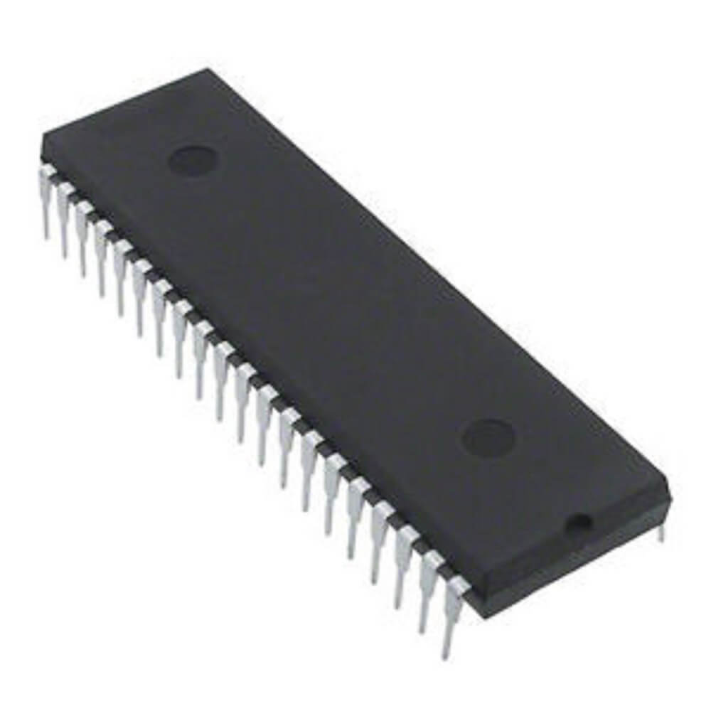
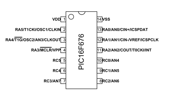
PIN Diagram of PIC16F84A
This is an 18 pin IC, the description of each pin are given below: ?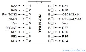
- It has thirtheen GPIO pins and each pin can be used either as digital input or digital output.
- These 13 GPIO pins are shared with PORTA and PORTB.
- PORTA consists of 5 pins from RA0-RA4 and PORTB has 8 pins from RB0-RB7.
Explanation of GPIO pins?
- Pins 1,2,3,6,7,8,9,10,11,12,13,17&18:
These 13 GPIO pins can be independently configured either as digital input or as digital output. Also, each pin can either supply or can absorb a maximum of 25mA current per pin. So, accordingly, every pin can drive a?قاد?easily but cannot drive any dc motor or relays. Because, current requirement for LED is generally less than 10mA and dc motor requires greater than 25mA.? ?If you want to interface relay or dc motor, you have to use current driver ICs. Like??motor driver IC?to interface motor and?relay driver IC?to interface single of multiple relays.? The mentioned 13 I/O pins are assembled into two groups known as ports.
- Port A:?contains 5 pins which are 1, 2, 3, 17 & 18 on pinout or RA0, RA1,RA2,RA3,RA4.
- Port B:?contains 8 pins which are 6, 7, 8, 9, 10, 11, 12 & 13 or RB0, RB1, RB2, RB3, RB4, RB5, RB6, RB7.
- Pin 4:?This is an active low pin known as MCLR (Memory Clear). Obviously, this pin is used to reset the device . Whenever it is kept low while connecting to the ground then it reset the device. Circuit below shows the reset circuit in blue color highlighted region. When user will press the push button, device will reset, otherwise it will remain on.
- Pin 5:?This is the ground pin of the IC and must be associated with the negative terminal of the battery or supply voltage.
- Pin 14:?This is a supply pin and must be connected to the positive terminal of the power supply. The operating voltage of this device is 5 volts.
- Pin 15 & 16:?This is where crystal oscillator connected and the maximum frequency can be used is 20MHz. you can also use a 4MHz crystal but the higher the frequency of crystal used, the quicker the controller works. Also, at higher frequeny, power consumption is also higher.? Picture given below shows the circuit diagram for oscillator circuit.? Connect both pins OSC1 and OSC2 across 20MHz crystal through two 22pF capacitors.
- You can also consult with the?ورقة البيانات?for further information.


Specifications?
| PIC16F84A | تحديد |
| Bus Width | 8 Bits |
| عدد الدبوس | 18 (PDIP, SOIC) / 20 (SSOP) |
| Processor Speed | 5 Million Instructions per second |
| Program Memory | 1750 Bytes |
| كبش | 68 Bytes |
| إيبروم | 64 Bytes |
Features of PIC16F84A microcontroller?
I/O Pins:?There are 13 I/O pins and these pins can be configured individually either as input or as output. Each of these pins source and sinks 25mA current.
Supports ICSP:?ICSP stands for In-Circuit Serial Programming. With little careful, you can program the microcontroller deprived of eliminating it from the target board for example in-circuit. This is widely used for in-circuit programming as it contains a USART module.
PIC16F84A Memory:?This PIC microcontroller comes with enhanced EEPROM memory. It contains 64 bytes memory that is mainly used to store data and 1K program memory specifies the capacity of code you can burn inside. 68 bytes of RAM (Data Memory).
Watchdog timer:?This microcontroller has built-in Watchdog timer. There is an internal timer located under the chip. You can make this timer enable or disable by programming. The timer is mainly used to rest the microcontroller when the program goes wrong or it may enter to the infinite loop.
Registers:?There are two types of registers which are as follow here.
- General Purpose Registers (GPR): These general purpose registers are used to store any arbitrary value in which you can operate.
- Special Function Registers (SFR). The special function registers are used to perform various functions which can help to control the device.
Timer: PIC16F84a contains one 8-bit timer that can be utilized in both ways i.e. timer and counter. Furthermore, accompanies internal and external clock select capability.
Sleep Mode:?This mode is included the chip that produces a low current power down mode. The sleep mode can be removed using an interrupt, external reset, and watchdog timer.
Power on Reset:?This feature is utilized in various other PIC microcontrollers when it is powered on. If there arises a problem in the chip, powering on the device will dismiss it from the loop of any malfunctioning in the device.
PIC16F84a Projects:?This version of PIC controllers are mostly used in students projects where the main concern is automation. This is also used in Central heating projects, Production of the temperature data logger, and gas sensor projects. Also used in security systems and setting up serial communication with other devices.
Compilers:?PIC controller has different compilers MPLAB C18 Compiler and MikroC Pro for a compiler. The code written in the compiler creates a hex record that is transferred on the PIC Microcontroller.
Ram Memory Banks: the RAM is consist of four banks. Before accessing any register during the time of programming or program writing, you must need to select the particular bank which contains that register. Handling banks may be steep if you write the code in assembly language.
USART module:?this microcontroller enhances with the USART module.
Flash Memory:?This consist of Flash memory based on 8-bit microcontroller packs. The same microcontroller device can be used for prototyping and production.