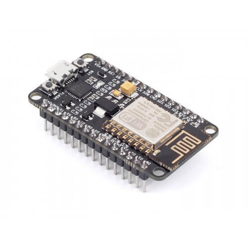


ESP8266 ESP-01S 5V WIFI RELAY MODULE INTERNET OF THINGS SMART HOME REMOTE CONTROL SWITCH FOR ARDUINO PHONE APP ESP01S WIRELESS WIFI MODULE
- 100% New and High Quality Wi-fi Smart Home Remote Control Switch
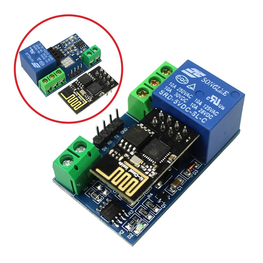
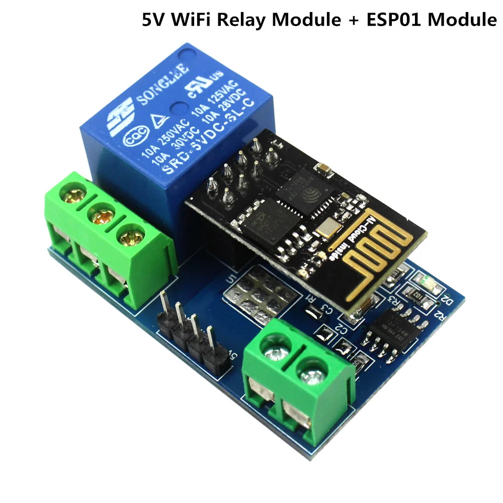
- ESP8266 ESP-01S 5V WiFi Internet Of Things Relay Module
- Control via Smart Phone (Android iPhone) by using ESP8266 App
- Transmission Distance: the maximum transmission distance is 400m
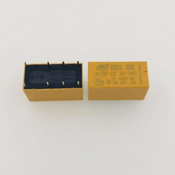
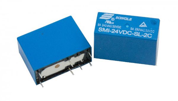
- Load: 10A / 250VAC 10A / 30VDC, the relay pull 100,000 times
- Note: Installation, Configuration and Use of this wifi relay module needs specialty in Electronics and IOT Development, Please don’t BUY if you don’t know how to program, setup and use it.
This WIFI relay based on AI-Thinker ESP-01S WIFI module. It is designed for smart home, Internet of thing and other DIY project. With this smart relay, you will easy to DIY your smart switch to control any device by your phone from anywhere.
THE FUNCTION AND CHARACTERISTICS of ESP8266 ESP-01 5V WiFi Relay Module
1. Onboard ESP8266 wifi module,In AP mode, it can be connected by 5 clients at the same time;
2. Wifi relay module has two work modes:
(1) cell phones carry on the wifi module directly;
(2) cell phone and wifi module carry on the same router;
3. Transmission distance:
(1) In the open environment, the maximum transmission distance is 400m when the cell phone carry on the wifi module directly ;
(2) when the wifi module and cell phone carrying on the same router ,the transmission distance depend on the router’ s signal intensity;
4. Onboard 5v, 10 A / 250 v AC 10 A / 30 v DC relay, absorb 100000 times continuously; Module with diode effusion protection, short response time;
Introduced the hardware and instructions of ESP8266 ESP-01 5V WiFi Relay Module
Size: 45mm x 28mm
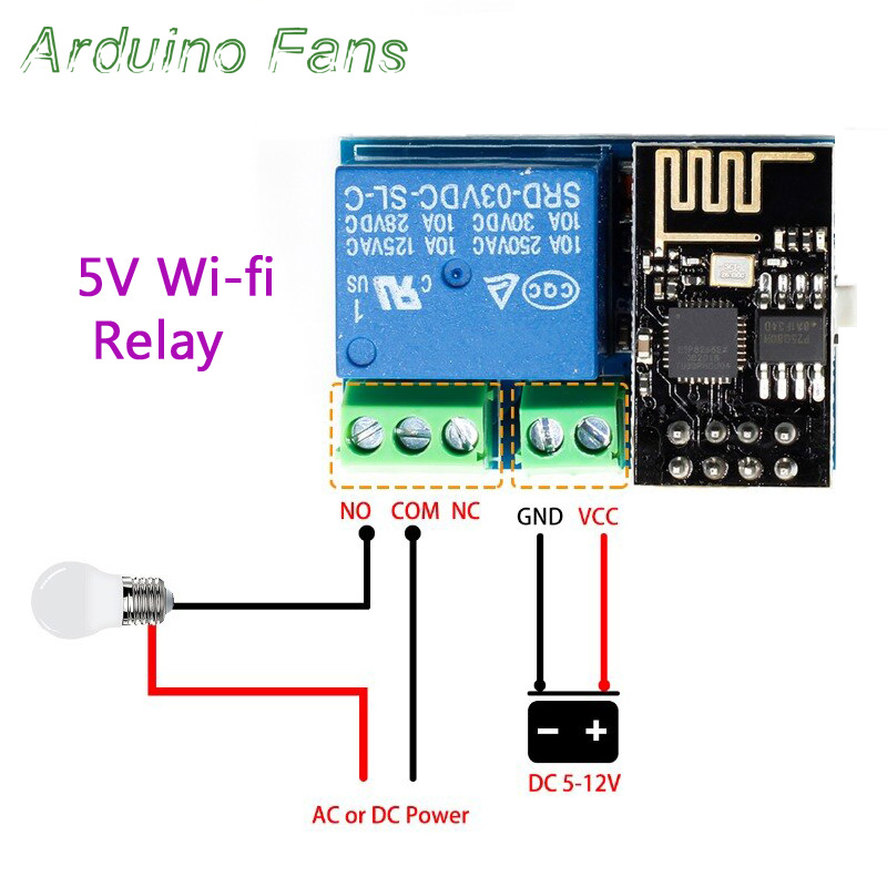
The board function description:
IN +,IN-: 5V power input;
TX ,RX and GND: serial port debug pins;
Instructions:
1. Onboard the ESP8266 wifi module has three work modes: STA (client), AP (hot), STA + AP( hot +client), According to the work mode of wifi relay module to choose the corresponding mode of ESP8266 wifi module .
2. Module need configuration by serial debugging software and USB to TTL module send serial command , TX ,RX ,GND pin of USB to TTL module connect to RX ,TX ,GND pin of ESP8266 relay module,and IN+,IN- connect to DC5V power.
3. The default Baud rate of wifi module maybe is 115200 or 9600,you can send AT command change it,such as: AT+CIOBAUD=115200. I recommend you use 115200 in general conditions, but you should change it to 9600 when you use cell phone control the relay(because the Baud rate of on board MCU STC15F104W is 9600).
Kindly Remind of ESP8266 ESP-01 5V WiFi Relay Module:
1. Wifi relay module need to reconfigure if restart
2. ESP8266 ESP-01 5V WiFi Relay Module has a timeout mechanism, when the cell phone haven’t sent commands to the ESP8266 wifi module over a period of time (default is 180s) , the ESP8266 wifi module will kick off your cell phone, you can send AT + CIPSTO = < time > on the PC to modify this time (time range 0-7200), such as: AT + CIPSTO = 3600.
3. If it not return OK and just return what you’ve sent commands when you use “USR-TCP232-Test-V1.3” configure the wifi module,you can press the ENTER before send commands
4. If it no response when you use “USR-TCP232-Test-V1.3” configure the wifi module, maybe the baud rate is incorrect,You can try 115200 or 9600. but when you use cell phone control the relay, you must make sure the baud rate of wifi module is 9600(send AT+CIOBAUD=9600 can change it),because the baud rate of onboard MCU(STC15F104W) is 9600
5. If you want to use a computer to control relay directly(baud rate is 9600), you can unplug the ESP8266 wifi module,and TX ,RX ,GND pin of USB to TTL module connect to TX ,RX ,GND pin of wifi relay module, IN+ and IN- connect to DC5V power. Send serial command(A00101A2 open relay; A00100A1 closed relay,command format must be hex) with serial debugging software on the PC to control the relay.
6.If the relay can’t open or close,maybe you need remove the R4, and use the USB to TTL module’s VCC pin connect to relay module’s 5V pin.
Installation steps
For work mode 1 (cell phones carry on the wifi module directly),Open the “USR-TCP232-Test-V1.3” Serial debugging software on the PC , send the flowing commands step by step:
1, AT+CWMODE=2, select AP mode;
2, AT+RST, reset;
3, AT+CIPMUX=1, open multiple connections;
4, AT+CIPSERVER=1,8080, configure the TCP server, set the port number;
5, AT+CIFSR, view the IP address in AP mode, such as: APIP, “192.168.4.1″;
6, AT+CIOBAUD=9600, set Baud rate to 9600.
7,Connect to the AP(Access Point) of ESP8266 wifi module on Android cell phone
8,Install the “EasyTCP_20” APP on the Android cell phone and open it, click “connect” and enter the IP address and port
9, Press the function blocks and enter the name and content of the serial command
(A00101A2 open relay,A00100A1 closed relay,command format must be hex)
10, Finally you can send serial command to control the relay by click the function blocks.
For work mode 2(cell phone and wifi module carry on the same router),Open the “USR-TCP232-Test-V1.3” Serial debugging software on the PC , send the flowing commands step by step:
1, AT+CWMODE=1, select STA mode;
2, AT+RST, reset;
3, AT+CWJAP=, , let WiFi module connect to the router, for example: AT+CWJAP=”LCTECH”,”12345678″;
4, AT+CIPMUX=1, open multiple connections;
5, AT+CIPSERVER=1,8080, configure the TCP server, set the port number;
6, AT+CIFSR, view the IP address in STA mode, such as: STAIP, “192.168.1.103”;
7,AT+CIOBAUD=9600,set Baud rate to 9600.
8, Using cell phone connect to the router
9,Install the “EasyTCP_20” APP on the Android cell phone and open it, click “connect” and enter the IP address and port
10, Press the function blocks and enter the name and content of the serial command (A00101A2 open relay,A00100A1 closed relay, command format must be hex)
11, Finally you can send serial command to control the relay by click the function blocks.
Tutorials for Programming
https://www.instructables.com/id/Simple-to-Implement-WiFI-Control-in-Your-Home/
https://evothings.com/how-to-connect-your-phone-to-your-esp8266-module/
https://www.instructables.com/id/ESP0101S-RELAY-MODULE-TUTORIAL/
| Transmission Distance (m) | 400 |
| Trigger Voltage (VDC) | 5 |
| Switching Voltage (VAC) | 250@10A |
| Switching Voltage (VDC) | 30@10A |
| Relay | 5V (10A/250V AC, 10A/30V DC) |
| Baud Rate | 9600 |
| Length (mm) | 36 |
| Width (mm) | 29 |
| Height (mm) | 17 |
| Weight (gm) | 17 |
| Shipment Weight | 0.025 kg |
| Shipment Dimensions | 6 × 9 × 2 cm |