IRF540N Pin Configuration
| Pin Number | Pin Name | Description |
| 1 | Source | Current flows out through Source |
| 2 | Gate | Controls the biasing of the MOSFET |
| 3 | Drain | Current flows in through Drain |
Features
- Small signal N-Channel MOSFET
- Continuous Drain Current (ID) is 33A at 25°C
- Pulsed Drain Current (ID-peak) is 110A
- Minimum Gate threshold voltage (VGS-th) is 2V
- Maximum Gate threshold voltage (VGS-th) is 4V
- Gate-Source Voltage is (VGS) is ±20V
- Maximum Drain-Source Voltage (VDS)is 100V
- Turn ON and Turn off time is 35ns each’
- It is commonly used with Arduino, due to its low threshold current.
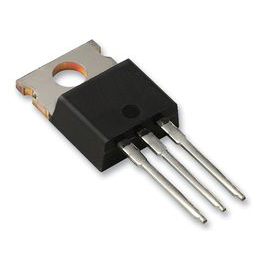
- Available in To-220 package
Note: Complete Technical Details can be found in the IRF540N datasheet given at the end of this page.
IRF540N Equivalent
RFP30N06, IRFZ44, 2N3055, IRF3205
Where to use IRF540N
The IRF540N is an N-Channel Mosfet. This mosfet can drive loads upto 23A and can support peak current upto 110A. It also has a threshold voltage of 4V, which means it can easily driven by low voltages like 5V. Hence it is mostly used with Arduino and other microcontrollers for logic switching. Speed control of motors and Light dimmers are also possible with this Mosfet since it has good switching characteristics.
So if you are looking for a Mosfet to switch applications that consume high current with some logic level devices, then this Mosfet will be a perfect choice for you.
How to use IRF540N
Unlike transistors, MOSFETs are voltage controlled devices. Meaning, they can be turned on or turned off by supplying the required Gate threshold voltage (VGS). IRF540N is an N-channel MOSFET, so the Drain and Source pins will be left open when there is no voltage applied to the gate pin. When a gate voltage is applied these pins gets closed.
The below circuit shows how this mosfet behaves when the Gate voltage is applied (5V) and not applied (0V). Since this an N-Channel mosfet the load that has to be switched (in this case a motor) should always be connected above the drain pin.
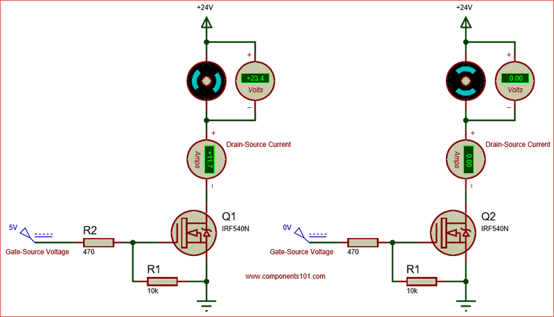
When you turn on a Mosfet by supplying the required voltage to the gate pin, it will remain on unless you supply 0V to the gate. To avoid this problem, we should always use a pull-down resistor (R1), here I have used a value of 10k. In applications like controlling the speed of motor or dimming a light we would use a PWM signal for fast switching, during this scenario, the MOSFET’s gate capacitance will create a reverse current due to parasitic effect. To tackle this we should use a current limiting capacitor, I have used a value of 470 here.
Applications
- Switching high power devices
- Control speed of motors
- LED dimmers or flashers
- High Speed switching applications
- Converters or Inverter circuits
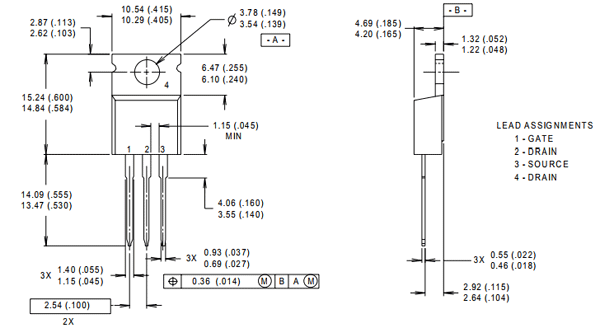
2D Model and Dimensions
If you are designing a PCB or Perf board with this component, then the following picture from the IRF540N Datasheet will be useful to know its package type and dimensions.