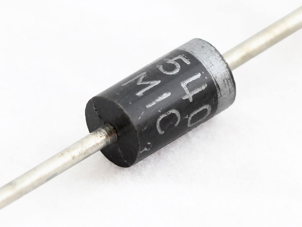
IRF630 N-Channel Power MOSFET Transistor
IRF630 is a third-generation power MOSFET specially designed for applications which required high-speed switching. This component is a great combination of low on-state resistance, cost-effective, and rugged design.
IRF630 is designed to sustain load voltage up to 200 V and 9 A current. It can drive current up to 36 A in pulse mode for 300 μs with a duty cycle of 2%. This Power MOSFET is specially designed to minimize input capacitance and gate change, and available in package TO-220.
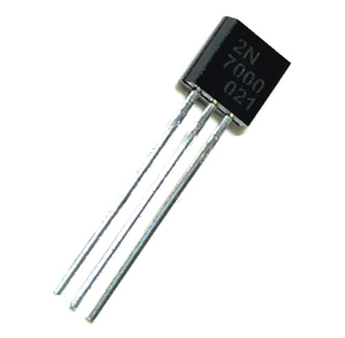
IRF630 Pinout Configuration
| Pin No | Pin Name | Pin description |
| 1 | Gate | Control the biasing of MOSFET |
| 2 | Drain | Current flows-in through Drain |
| 3 | Source | Current flows-out through Source |
Features
- Extremely high dv/dt capability
- Fast switching
- Low intrinsic capacitance
- Ease of paralleling
- Gate charge minimized
- Simple drive requirement
IRF630 Equivalent MOSFETs
IRF630 can be replaced by IRFS630, IRFS631, IRF630PBF, IRF640, IRF640PBF, IRF644, IRFB17N50L.
Applications
The application of IRF630 is as listed below;
- Solar power supply application
- Motor drivers
- Battery charger
- Telecommunication applications
- High-speed switching applications
- Power management
- Portable devices
Technical Specifications
- Transistor type: N-channel
- Maximum applied voltage from drain-to-source (VDS): 200 V
- Maximum Drain current (continuous) ID: 9 A
- Maximum Drain Current (Pulse): 36 A
- Maximum Power dissipation: 74 W
- On-state resistance between drain and source: 0.40 Ω
- gate-to-source voltage: ±20 V
- Gate charge QD: 43 nC
- Dynamic dv/dt ruggedness: 5.8 V/ns
- Operating junction and storage temperature range: -55 to 150 ˚C
- Package: TO-220
Note: More technical specifications can be found on the IRF630 datasheet attached at the bottom of this page.
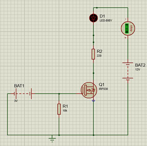
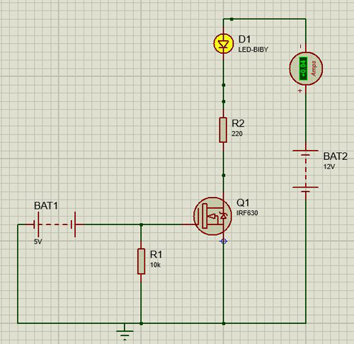
IRF630 MOSFET Working with Simulation
A MOSFET can be turned ON by supplying proper gate voltage between the gate and source terminal. If the gate voltage is not applied properly, the MOSFET will remain turn OFF condition. For example, we take IRF630 as MOSFET and use this MOSFET as a switching device to turn ON and OFF a LED. The simulation is done in proteus.
Condition-1: When the applied gate voltage is more than 4 V, the LED will turn ON. Here, we apply 5 V between gate and source.
Condition-2: When the applied gate voltage is less than 4 V, the LED remains in OFF condition. In this example, the applied gate voltage is 3V, and the LED seems in OFF condition in the figure below.