
Save
-28%
Out of stock
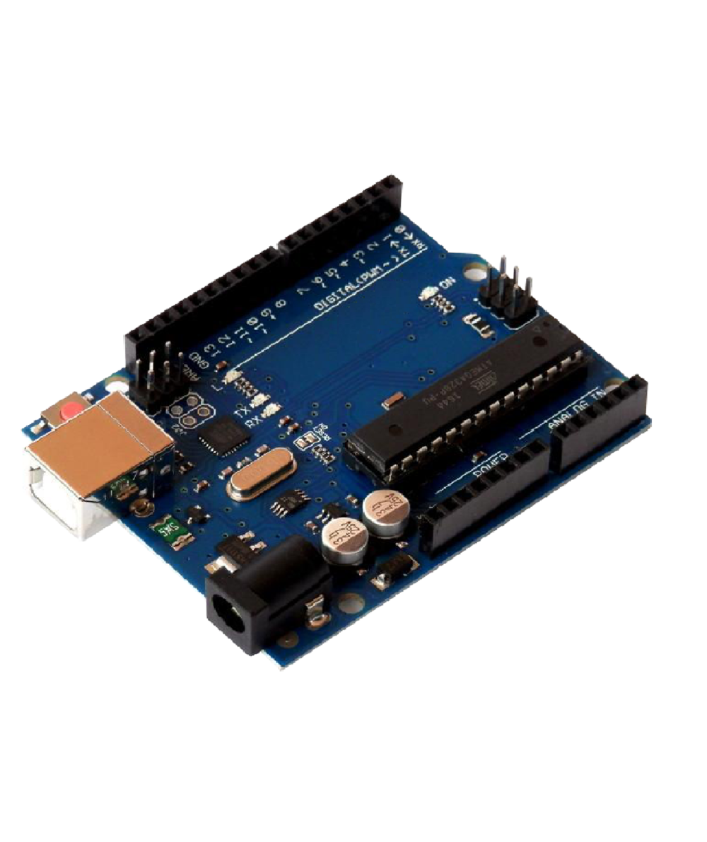
Arduino Uno R3 Board without Cable High Quality
Original price was: 500.00 EGP.360.00 EGPCurrent price is: 360.00 EGP.
Arduino Uno R3 Board without Cable High Quality
- Micro-controller : ATmega328.
- Operating Voltage : 5V.
- Input Voltage (recommended) : 7-12V.
- Digital I/O Pins : 14 (of which 6 provide PWM output).
- Analog Input Pins : 6.
Quantities are confirmed after reviewing
your order. Orders are normally prepared
and shipped within 3–5 business days.
Online availability does not necessarily
mean the product is currently available
at the branch.
تأكيد الكميات بيتم بعد مراجعة الأوردر،
وتجهيز وشحن الطلب بيستغرق عادة من
3 إلى 5 أيام عمل.
توافر المنتج على الموقع لا يعني بالضرورة
توافره داخل الفرع، لذلك اعمل الأوردر
مسبقًا لتأكيد الكمية وتجهيزه.
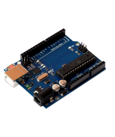
This item: Arduino Uno R3 Board without Cable High Quality
Original price was: 500.00 EGP.360.00 EGPCurrent price is: 360.00 EGP.
Original price was: 500.00 EGP.360.00 EGPCurrent price is: 360.00 EGP.
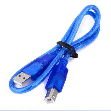
Original price was: 25.00 EGP.20.00 EGPCurrent price is: 20.00 EGP.
Fast shipping
Delivery across Egypt
Flexible payment
Cash and online options
Quantity confirmation
Confirmed after order review
Technical support
Help choosing compatible parts
- Description
Description
BUY Arduino Uno R3 Board without Cable in Egypt
The Uno R3 without Cable is a micro-controller board base on the ATmega328 (datasheet). It has 14 digital input/output pins (of which 6 can be used as PWM outputs); 6 analog inputs, a 16 MHz ceramic resonator, a USB connection, a power jack, an ICSP header, and a reset button.It contains everything need to support the microcontroller; simply connect it to a computer with a USB cable or power it with an AC-to-DC adapter or battery to get started.“Uno” means one in Italian and is the name to mark the upcoming release of Arduino 1.0. The Uno and version 1.0 will be the reference versions of Arduino, moving forward. The Uno is the latest in a series of USB Arduino boards and the reference model for the Arduino platform; for a comparison with previous versions, see the index of Arduino boards.
Note: The Uno R3 reference design can use an Atmega8, 168, or 328, Current models use an ATmega328, but an Atmega8 is shown in the schematic for reference. The pin configuration is identical on all three processors.
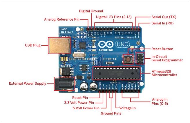 Power for Arduino uno
The Uno R3 can be powered via the USB connection or with an external power supply. The power source is selected automatically.
External (non-USB) power can come either from an AC-to-DC adapter (wall-wart) or battery. The adapter can be connected by plugging a 2.1mm center-positive plug into the board’s power jack. Leads from a battery can be inserted in the Gnd and Vin pin headers of the POWER connector.
The board can operate on an external supply of 6 to 20 volts. If supplied with less than 7V, however, the 5V pin may supply less than five volts and the board may be unstable. If using more than 12V, the voltage regulator may overheat and damage the board. The recommended range is 7 to 12 volts.
The power pins are as follows :
- VIN. The input voltage to the Arduino board when it’s using an external power source (as opposed to 5 volts from the USB connection or another regulated power source). You can supply voltage through this pin, or, if supplying voltage via the power jack, access it through this pin.
- 5V.This pin outputs a regulated 5V from the regulator on the board. The board can be supplied with power either from the DC power jack (7 – 12V), the USB connector (5V), or the VIN pin of the board (7-12V). Supplying voltage via the 5V or 3.3V pins bypasses the regulator, and can damage your board. We don’t advise it.
- 3V3. A 3.3 volt supply generated by the onboard regulator. The maximum current draw is 50 mA.
- GND. Ground pins.
- IOREF. This pin on the Arduino board provides the voltage reference with which the microcontroller operates. A properly configured shield can read the IOREF pin voltage and select the appropriate power source or enable voltage translators on the outputs for working with the 5V or 3.3V.
Memory of Arduino uno :
The ATmega328 has 32 KB (with 0.5 KB used for the bootloader). It also has 2 KB of SRAM and 1 KB of EEPROM (which can be read and written with the EEPROM library).
Input and Output of Arduino uno
Each of the 14 digital pins on the Uno can be used as an input or output, using pinMode(), digitalWrite(), and digitalRead() functions. They operate at 5 volts. Each pin can provide or receive a maximum of 40 mA and has an internal pull-up resistor (disconnected by default) of 20-50 kOhms. In addition, some pins have specialized functions:
- Serial: 0 (RX) and 1 (TX). Used to receive (RX) and transmit (TX) TTL serial data. These pins are connected to the corresponding pins of the ATmega8U2 USB-to-TTL Serial chip.
- External Interrupts 2 and 3. These pins can be configured to trigger an interrupt on a low value, a rising or falling edge, or a change in value. See the attachInterrupt() function for details.
- PWM: 3, 5, 6, 9, 10, and 11. Provide 8-bit PWM output with the analogWrite() function.
- SPI: 10 (SS), 11 (MOSI), 12 (MISO), 13 (SCK). These pins support SPI communication using the SPI library.
- LED: 13. There is a built-in LED connected to digital pin 13. When the pin is HIGH value, the LED is on, when the pin is LOW, it’s off.
The Uno R3 has 6 analog inputs, labeled A0 through A5, each of which provides 10 bits of resolution (i.e. 1024 different values). By default, they measure from ground to 5 volts, though is it possible to change the upper end of their range using the AREF pin and the analogReference() function. Additionally, some pins have specialized functionality:
- TWI: A4 or SDA pin and A5 or SCL pin. Support TWI communication using the Wire library.
There are a couple of other pins on the board:
- AREF. A reference voltage for the analog inputs. Used with analogReference().
- Reset. Bring this line LOW to reset the microcontroller. Typically used to add a reset button to shields which block the one on the board.
See also the mapping between Arduino pins and ATmega328 ports. The mapping for the Atmega8, 168, and 328 is identical.
Communication of Arduino uno R3
The Uno R3 has a number of facilities for communicating with a computer, another Arduino, or other microcontrollers. The ATmega328 provides UART TTL (5V) serial communication, which is available on digital pins 0 (RX) and 1 (TX). An ATmega16U2 on the board channels this serial communication over USB and appears as a virtual com port to software on the computer. The ’16U2 firmware uses the standard USB COM drivers, and no external driver is needed. However, on Windows, a .inf file is required. The Arduino software includes a serial monitor which allows simple textual data to be sent to and from the Arduino board. The RX and TX LEDs on the board will flash when data is being transmitted via the USB-to-serial chip and USB connection to the computer (but not for serial communication on pins 0 and 1).
A SoftwareSerial library allows for serial communication on any of the Uno’s digital pins.
The ATmega328 also supports I2C (TWI) and SPI communication. The Uno R3 software includes a Wire library to simplify use of the I2C bus; see the documentation for details. For SPI communication, use the SPI library.
Programming of Arduino uno R3
The Uno R3 can be a program with the Arduino software (download). Select “Arduino Uno from the Tools > Board menu (according to the microcontroller on your board). For details, see the reference and tutorials.
The ATmega328 on the Uno R3 comes pre-burn with a bootloader that allows you to upload new code to it without the use of an external hardware programmer. It communicates using the original STK500 protocol (reference, C header files).
You can also bypass the bootloader and program the microcontroller through the ICSP (In-Circuit Serial Programming) header; see these instructions for details.
The ATmega16U2 (or 8U2 in the rev1 and rev2 boards) firmware source code is available. The ATmega16U2/8U2 is load with a DFU bootloader, which can be activated by:
- On Rev1 boards: connecting the solder jumper on the back of the board (near the map of Italy) and then resetting the 8U2.
- On Rev2 or later boards: there is a resistor that pulling the 8U2/16U2 HWB line to ground, making it easier to put into DFU mode.
You can then use Atmel’s FLIP software (Windows) or the DFU programmer (Mac OS X and Linux) to load a new firmware. Or you can use the ISP header with an external programmer (overwriting the DFU bootloader). See this user-contributed tutorial for more information.
Automatic (Software) Reset of Arduino uno R3
Rather than requiring a physical press of the reset button before an upload, the Arduino Uno is designed in a way that allows it to be reset by software running on a connected computer. One of the hardware flow control lines (DTR) of theATmega8U2/16U2 is connected to the reset line of the ATmega328 via a 100 nano-farad capacitor. When this line is asserted (taken low), the reset line drops long enough to reset the chip. The Arduino software uses this capability to allow you to upload code by simply pressing the upload button in the Arduino environment. This means that the boot-loader can have a shorter timeout, as the lowering of DTR can be well-coordinated with the start of the upload.
This setup has other implications. When the Uno is connected to either a computer running Mac OS X or Linux, it resets each time a connection is made to it from software (via USB). For the following half-second or so, the boot-loader is running on the Uno. While it is a program to ignore malformed data (i.e. anything besides an upload of new code), it will intercept the first few bytes of data sent to the board after a connection is open. If a sketch running on the board receives one-time configuration or other data when it first starts, makes sure that the software with which it communicates waits for a second after opening the connection and before sending this data.
The Uno R3 contains a trace that can be cut to disable the auto-reset. The pads on either side of the trace can be soldered together to re-enable it. It’s label “RESET-EN”. You may also be able to disable the auto-reset by connecting a 110-ohm resistor from 5V to the reset line; see this forum thread for details.
USB Overcurrent Protection
The Arduino Uno has a resettable polyfuse that protects your computer’s USB ports from shorts and overcurrent. Although most computers provide their own internal protection, the fuse provides an extra layer of protection. If more than 500 mA is applied to the USB port, the fuse will automatically break the connection until the short or overload is removed.
Physical Characteristics
The maximum length and width of the Uno PCB are 2.7 and 2.1 inches respectively, with the USB connector and power jack extending beyond the former dimension. Four screw holes allow the board to be attached to a surface or case. Note that the distance between digital pins 7 and 8 is 160 mil (0.16″), not an even multiple of the 100 mil spacing of the other pins.
Note: If you are getting the error while uploading the code in the Arduino Uno or not detecting the port need to upload the bootloader.
Features :
- 1.0 pinout: added SDA and SCL pins that are near to the AREF pin and two other new pins placed near to the RESET pin, the IOREF that allow the shields to adapt to the voltage provided from the board. In future, shields will be compatible with both the board that uses the AVR, which operates with 5V and with the Arduino Due that operates with 3.3V. The second one is a not connected pin, that is the reserve for future purposes.
- Stronger RESET circuit.
- Atmega 16U2 replace the 8U2.
Package Includes :
1 x Uno R3 Board without Cable compatible with Arduino
Useful Links:
Getting Started with Arduino and Genuino products
| Color | Blue |
| DC Current per I/O Pin (mA) | 50 |
| Digital I/O Pins | 14 (of which 6 provide PWM output) |
| EEPROM | 1 KB (ATmega328) |
| Flash Memory | 32 KB |
| Input Voltage(Recommended) | 7-12V |
| Operating Voltage (VDC) | 5 |
| PWM Output Pins | 6 |
| SRAM | 2 |
| Weight (gm) | 26 |
| Shipment Weight | 0.03 kg |
| Shipment Dimensions | 10 × 6 × 4 cm |
اشترِ لوحة Arduino Uno R3 بدون كابل في مصر
لوحة Uno R3 بدون كابل هي لوحة متحكم دقيق مبنية على الشريحة ATmega328.
تحتوي على 14 طرف إدخال/إخراج رقمي، منها 6 أطراف يمكن استخدامها كمخارج PWM، بالإضافة إلى 6 مداخل تناظرية، ومذبذب سيراميكي بتردد 16 ميجاهرتز، ومنفذ USB، ومدخل طاقة، ورأس ICSP، وزر Reset.
تتضمن اللوحة كل ما يلزم لتشغيل المتحكم الدقيق؛ فقط قم بتوصيلها بالكمبيوتر باستخدام كابل USB أو قم بتغذيتها من خلال محول كهربائي AC إلى DC أو بطارية للبدء.
كلمة Uno تعني واحد بالإيطالية، وتم اختيار هذا الاسم للإشارة إلى الإصدار القادم من Arduino 1.0. وتُعتبر لوحة Uno والإصدار 1.0 المرجع الأساسي لمنصة أردوينو. وتُعد Uno أحدث لوحة ضمن سلسلة لوحات أردوينو المزودة بمنفذ USB، وهي النموذج المرجعي لمنصة Arduino.
ملاحظة:
يمكن أن يستخدم التصميم المرجعي لـ Uno R3 الشريحة ATmega8 أو ATmega168 أو ATmega328. الموديلات الحالية تستخدم ATmega328، ولكن قد تظهر ATmega8 في بعض المخططات بغرض المرجع فقط. ترتيب الأطراف متماثل في جميع هذه المعالجات.
تغذية الطاقة للوحة Arduino Uno
يمكن تشغيل Uno R3 عن طريق منفذ USB أو من خلال مصدر طاقة خارجي، ويتم اختيار مصدر الطاقة تلقائيًا.
يمكن أن تأتي الطاقة الخارجية من:
- محول AC إلى DC
- أو بطارية
يمكن توصيل المحول عن طريق فيشة 2.1 مم موجب في المنتصف في مدخل الطاقة الموجود على اللوحة. كما يمكن توصيل البطارية عبر أطراف GND و VIN الموجودة في موصل الطاقة.
يمكن للوحة العمل بجهد خارجي من 6 إلى 20 فولت.
ولكن إذا كان الجهد أقل من 7 فولت فقد يقل الجهد الخارج من طرف 5V عن 5 فولت، وقد تصبح اللوحة غير مستقرة.
أما إذا زاد الجهد عن 12 فولت فقد يسخن منظم الجهد بشكل زائد مما قد يؤدي إلى تلف اللوحة.
لذلك فإن الجهد الموصى به هو من 7 إلى 12 فولت.
أطراف الطاقة
- VIN:
جهد الإدخال إلى لوحة أردوينو عند استخدام مصدر طاقة خارجي، بدلًا من 5 فولت القادمة من USB أو من مصدر منظم آخر. يمكنك تغذية اللوحة عبر هذا الطرف، أو الوصول إلى الجهد القادم من مدخل الطاقة من خلاله. - 5V:
هذا الطرف يخرج 5 فولت منظم من منظم الجهد الموجود على اللوحة. يمكن تغذية اللوحة من خلال مدخل الطاقة DC (7 إلى 12 فولت)، أو عبر USB (5 فولت)، أو من خلال طرف VIN (7 إلى 12 فولت).
لا يُنصح بتغذية اللوحة مباشرة عبر طرفي 5V أو 3.3V لأن ذلك يتجاوز منظم الجهد وقد يتسبب في تلف اللوحة. - 3V3:
جهد 3.3 فولت يتم توليده من منظم الجهد على اللوحة، وأقصى تيار يمكن سحبه منه هو 50 ملي أمبير. - GND:
أطراف الأرضي. - IOREF:
هذا الطرف يوفر جهد المرجع الذي يعمل به المتحكم الدقيق. ويمكن للوحدات الإضافية المتوافقة أن تقرأ هذا الجهد لتحديد مصدر الطاقة المناسب أو تفعيل محولات الجهد عند المخارج للعمل مع 5V أو 3.3V.
ذاكرة Arduino Uno
تحتوي الشريحة ATmega328 على:
- 32 كيلوبايت من ذاكرة الفلاش، يُستخدم منها 0.5 كيلوبايت للـ Bootloader
- 2 كيلوبايت SRAM
- 1 كيلوبايت EEPROM
ويمكن القراءة والكتابة على EEPROM باستخدام مكتبة EEPROM.
الإدخال والإخراج في Arduino Uno
يمكن استخدام كل طرف من الأطراف الرقمية الأربعة عشر في لوحة Uno كمدخل أو مخرج باستخدام الدوال:
pinMode()digitalWrite()digitalRead()
تعمل هذه الأطراف عند 5 فولت، ويمكن لكل طرف توفير أو استقبال تيار أقصى 40 ملي أمبير، كما يحتوي كل طرف على مقاومة سحب لأعلى داخلية بقيمة تتراوح بين 20 إلى 50 كيلوأوم وتكون غير مفعلة افتراضيًا.
وظائف خاصة لبعض الأطراف
- Serial: 0 (RX) و 1 (TX)
تُستخدم لاستقبال وإرسال البيانات التسلسلية TTL، وهي متصلة بشريحة التحويل USB إلى TTL. - External Interrupts: 2 و 3
يمكن إعداد هذه الأطراف لتفعيل مقاطعة عند مستوى منخفض، أو حافة صاعدة أو هابطة، أو عند تغير القيمة. - PWM: 3 و5 و6 و9 و10 و11
توفر خرج PWM بدقة 8-بت باستخدام الدالةanalogWrite(). - SPI: 10 (SS)، 11 (MOSI)، 12 (MISO)، 13 (SCK)
تدعم الاتصال عبر بروتوكول SPI باستخدام مكتبة SPI. - LED: الطرف 13
يوجد LED مدمج متصل بالطرف الرقمي 13. عندما تكون قيمة الطرف HIGH يضيء الليد، وعندما تكون LOW ينطفئ.
المداخل التناظرية
تحتوي لوحة Uno R3 على 6 مداخل تناظرية من A0 إلى A5، وكل مدخل يوفر دقة 10-بت، أي 1024 قيمة مختلفة.
بشكل افتراضي تقيس هذه المداخل الجهد من الأرضي حتى 5 فولت، ولكن يمكن تغيير الحد الأعلى باستخدام طرف AREF والدالة analogReference().
وظائف إضافية
- TWI / I2C:
الطرف A4 أو SDA والطرف A5 أو SCL يدعمان الاتصال عبر بروتوكول TWI/I2C باستخدام مكتبة Wire.
أطراف أخرى على اللوحة
- AREF:
جهد مرجعي للمداخل التناظرية، ويُستخدم معanalogReference(). - Reset:
عند جعل هذا الطرف في مستوى LOW يتم إعادة تشغيل المتحكم الدقيق. ويُستخدم عادة لإضافة زر إعادة تشغيل في الوحدات الإضافية التي قد تغطي زر Reset الموجود على اللوحة.
الاتصال في Arduino Uno R3
توفر لوحة Uno R3 عدة وسائل للاتصال مع الكمبيوتر أو لوحة أردوينو أخرى أو متحكمات دقيقة أخرى.
توفر الشريحة ATmega328 اتصالًا تسلسليًا من نوع UART TTL 5V، وهو متاح على الطرفين:
- 0 (RX)
- 1 (TX)
وتقوم الشريحة ATmega16U2 الموجودة على اللوحة بتحويل هذا الاتصال التسلسلي إلى USB ليظهر على الكمبيوتر كمنفذ COM افتراضي.
تستخدم الشريحة 16U2 تعريفات USB القياسية، لذلك لا يتطلب الأمر تعريفًا خارجيًا في أغلب الحالات، ولكن في Windows قد يكون ملف .inf مطلوبًا.
يتضمن برنامج Arduino أداة Serial Monitor التي تسمح بإرسال واستقبال البيانات النصية بسهولة. كما تومض لمبات RX و TX أثناء نقل البيانات عبر USB.
تتيح مكتبة SoftwareSerial إمكانية الاتصال التسلسلي على أي طرف رقمي تقريبًا.
كما تدعم الشريحة ATmega328 أيضًا بروتوكولي:
- I2C / TWI
- SPI
برمجة Arduino Uno R3
يمكن برمجة Uno R3 باستخدام برنامج Arduino IDE.
يتم اختيار Arduino Uno من قائمة:
Tools > Board
تأتي الشريحة ATmega328 على اللوحة محمّلة مسبقًا ببرنامج Bootloader، والذي يسمح برفع الكود دون الحاجة إلى مبرمج خارجي.
كما يمكن تجاوز الـ Bootloader وبرمجة المتحكم مباشرة عبر رأس ICSP.
البرنامج الثابت الخاص بالشريحة ATmega16U2 / 8U2 متاح أيضًا، وتكون هذه الشريحة مزودة بـ DFU Bootloader.
إعادة الضبط التلقائي
تم تصميم لوحة Arduino Uno بحيث يمكن إعادة تشغيلها برمجيًا من الكمبيوتر دون الحاجة إلى الضغط يدويًا على زر Reset قبل رفع الكود.
يتم ذلك من خلال خط DTR في الشريحة ATmega8U2/16U2، المتصل بخط Reset الخاص بالشريحة ATmega328 عبر مكثف 100 نانوفاراد.
عند تفعيل هذا الخط يتم إعادة تشغيل المتحكم لفترة كافية لبدء تحميل البرنامج.
هذا يسهل رفع الأكواد من خلال الضغط فقط على زر Upload في بيئة Arduino.
حماية USB من زيادة التيار
تحتوي لوحة Arduino Uno على فيوز قابل لإعادة الضبط لحماية منفذ USB في الكمبيوتر من القصر الكهربائي أو زيادة التيار.
إذا زاد التيار عن 500 ملي أمبير، يقوم الفيوز بفصل الاتصال تلقائيًا حتى يتم إزالة سبب الحمل الزائد أو القصر.
الخصائص الفيزيائية
الطول والعرض الأقصى للوحة:
- الطول: 2.7 بوصة
- العرض: 2.1 بوصة
يوجد 4 ثقوب تثبيت تسمح بتركيب اللوحة على سطح أو داخل صندوق.
كما يجب ملاحظة أن المسافة بين الطرفين الرقميين 7 و8 هي 160 mil وليست مضاعفًا منتظمًا للمسافة القياسية بين باقي الأطراف.
ملاحظة مهمة
إذا ظهرت مشكلة أثناء رفع الكود على لوحة Arduino Uno أو لم يتم التعرف على المنفذ، فقد تحتاج إلى رفع Bootloader مرة أخرى.
المميزات
- تخطيط أطراف 1.0
- إضافة طرفي SDA و SCL بالقرب من AREF
- إضافة أطراف جديدة بالقرب من RESET
- وجود طرف IOREF لتمكين الوحدات الإضافية من التوافق مع جهد اللوحة
- دائرة RESET أقوى
- استبدال شريحة ATmega8U2 بـ ATmega16U2
محتويات العبوة
- 1 × لوحة Uno R3 بدون كابل متوافقة مع Arduino
المواصفات الفنية
- اللون: أزرق
- التيار المستمر لكل طرف I/O: 50 ملي أمبير
- عدد الأطراف الرقمية: 14 (منها 6 مخارج PWM)
- EEPROM: 1 كيلوبايت
- Flash Memory: 32 كيلوبايت
- جهد الإدخال الموصى به: 7 – 12 فولت
- جهد التشغيل: 5 فولت DC
- عدد مخارج PWM: 6
- SRAM: 2 كيلوبايت
- الوزن: 26 جم
- وزن الشحن: 0.03 كجم
- أبعاد الشحن: 10 × 6 × 4 سم
You May Also Like
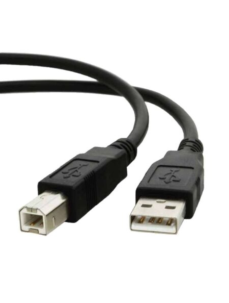
Cable For Arduino UNO/MEGA (USB A to B) 30cm
Original price was: 25.00 EGP.20.00 EGPCurrent price is: 20.00 EGP.
Related Products
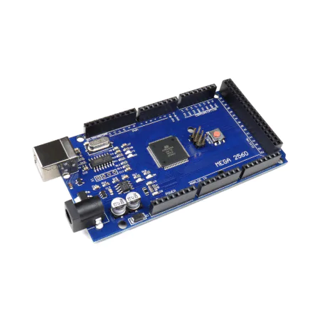
Arduino Mega 2560 R3 CH340G ATmel MCU ATMEGA2560-16U Improved Version CH340G Board (Board Only)
Original price was: 1,500.00 EGP.1,200.00 EGPCurrent price is: 1,200.00 EGP.
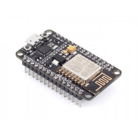
NodeMCU Based ESP8266 Development Kit CP2102 v2
Original price was: 270.00 EGP.220.00 EGPCurrent price is: 220.00 EGP.
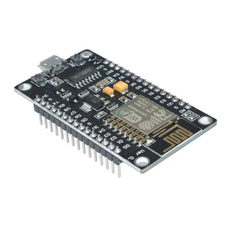
NodeMcu ESP8266 V3 CH340 Wifi Developed Board good Quality
Original price was: 240.00 EGP.180.00 EGPCurrent price is: 180.00 EGP.
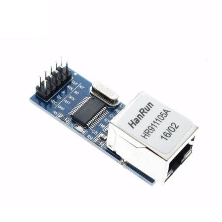
MiNi ENC28J60 Ethernet LAN Network Module For Arduino SPI AVR PIC LPC
Original price was: 350.00 EGP.250.00 EGPCurrent price is: 250.00 EGP.

Uno+WiFi R3 AtMega328p+NodeMCU ESP8266 8mb Memory USB-TTL CH340G Compatible for Arduino UNO
Original price was: 750.00 EGP.500.00 EGPCurrent price is: 500.00 EGP.
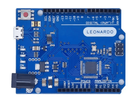
Arduino Leonardo — ATmega32U4 Board with Native USB HID, 20 I/O, 7 PWM
Original price was: 550.00 EGP.490.00 EGPCurrent price is: 490.00 EGP.

Arduino UNO R4 Wifi Improved Version Type-C Made In China
Original price was: 1,500.00 EGP.1,100.00 EGPCurrent price is: 1,100.00 EGP.
Products With Similar Tags
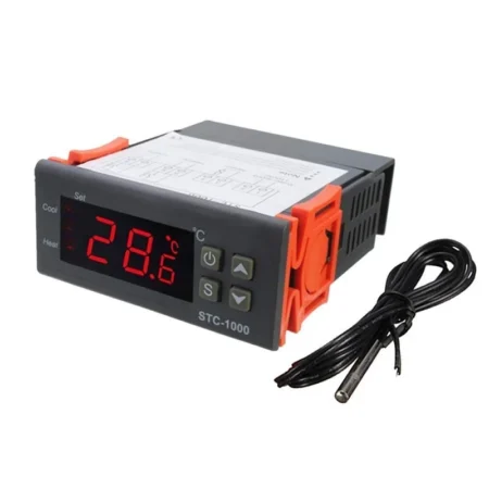
Temperature Meter & Controllers, ❤️ Big Discount Days..!💲🏷️Electronics Sales, Digital Measuring Devices, Temperature & Humidity Sensor
STC-1000 AC 220V Digital Temperature Controlled Thermostat Switch STC1000
Original price was: 340.00 EGP.320.00 EGPCurrent price is: 320.00 EGP.
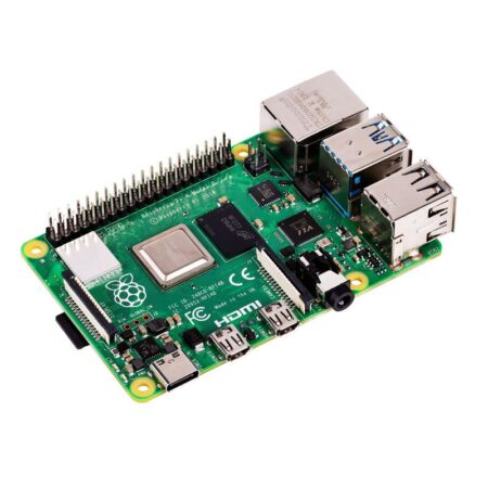
Raspberry Pi 4 Model-B with 4 GB RAM
Original price was: 8,000.00 EGP.7,400.00 EGPCurrent price is: 7,400.00 EGP.
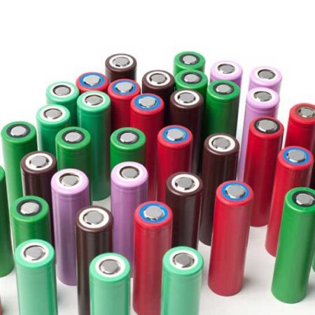
18650 Li-ion Battery 3.7v Rechargeable ICR (Recycled) 1000-1500mA
Original price was: 50.00 EGP.40.00 EGPCurrent price is: 40.00 EGP.

Power Supply SMPS 12V 42A With Fan (S-500-12)
Original price was: 1,500.00 EGP.1,200.00 EGPCurrent price is: 1,200.00 EGP.
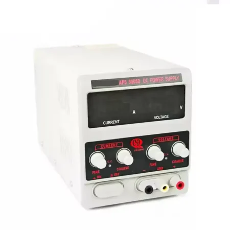
DC Regulated Power Supply M&R APS3005D 5A
Original price was: 3,000.00 EGP.2,850.00 EGPCurrent price is: 2,850.00 EGP.

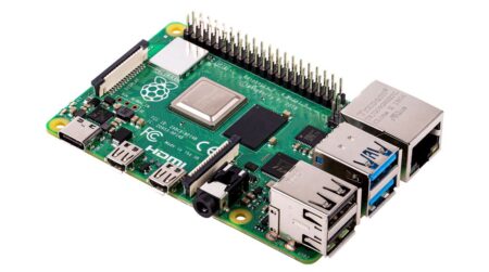
Raspberry Pi 4 Model B with 2 GB RAM
Original price was: 7,000.00 EGP.5,600.00 EGPCurrent price is: 5,600.00 EGP.
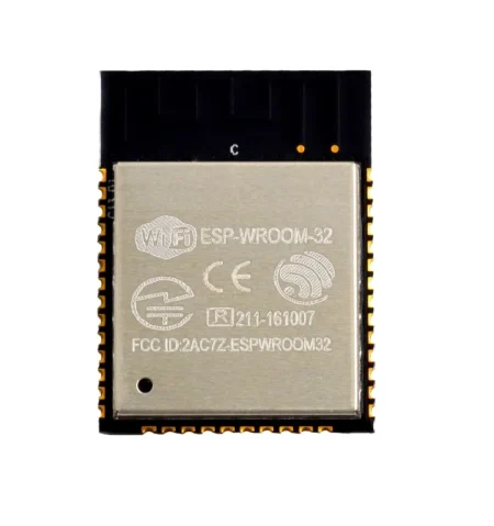
ESP-WROOM-32 Wifi Bluetooth Combo Module ESP32 Chip SMD
Original price was: 400.00 EGP.325.00 EGPCurrent price is: 325.00 EGP.
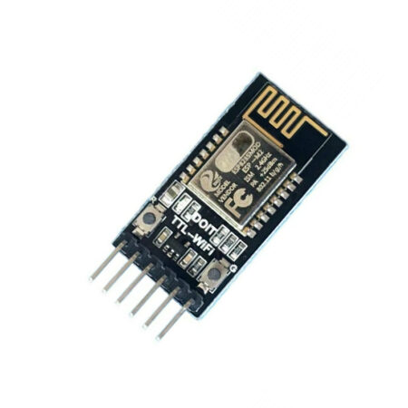
DT-06 WiFi Serial Port Transparent Transmission Module TTL to WIFI Compatible with BT HC-06 Interface ESP-M2
Original price was: 300.00 EGP.270.00 EGPCurrent price is: 270.00 EGP.

LED Strip Addressable RGB 5V 60LED/m IP20 5meter Roll SMD2812
Original price was: 950.00 EGP.750.00 EGPCurrent price is: 750.00 EGP.

LM35DZ Temperature Sensor – Original Analog IC
Original price was: 120.00 EGP.100.00 EGPCurrent price is: 100.00 EGP.

IR Encoder Photoelectric Sensor 4-pin
Original price was: 60.00 EGP.50.00 EGPCurrent price is: 50.00 EGP.