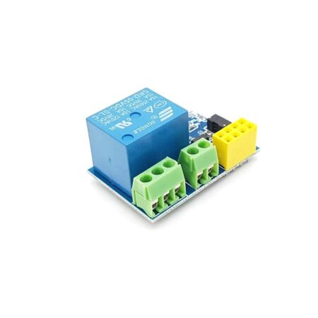
Relay 5v 2 Channel Module 2 Road/Channel Relay Module (with light coupling) 5V HW-383
- Low Level Trigger Relay Module
- Two separate LEDs for On/Off indication of the Relay.
- Triggering input voltage 3.3V – 5V
- Two separate LEDs for On/Off indication of the Relay
- Triggering input voltage 3.3V – 5V 4)
- Back EMF protection
- Back EMF protection 2 LEDs to indicate when relays are ON.
- Works with logic level signals from 3.3V or 5V devices
- Opto isolation circuitry
- Module with diode current protection, short response time
- AC Control Voltage: 250V @max.10A
- DC Control Voltage: 30V @max. 10A
- Description
Description
Relay 5v 2 Channel Module 2 Road/Channel Relay Module (with light coupling) 5V HW-383
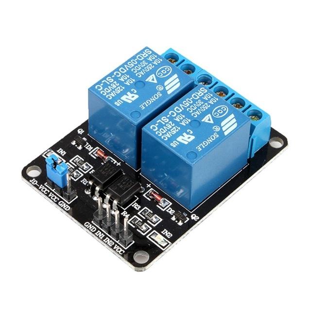
This is a 2 Channel isolated 5V 10A relay module Optocoupler for Arduino PIC ARM. It can be used to control various appliances and other types of equipment with a large current. It can be controlled directly with 3.3V or 5V logic signals from a microcontroller (Arduino, 8051, AVR, PIC, DSP, ARM, ARM, MSP430, TTL logic).
This relay has a 1×4 (2.54mm pitch) pin header for connecting power (5V and 0V), and for controlling the 2 relays.
The pins are marked on the PCB as:
- GND – Connect 0V to this pin.
- IN1 – Controls relay 1, active Low Relay will turn on when this input goes below about 2.0V
- IN2 – Controls relay 2, active Low Relay will turn on when this input goes below about 2.0V
- VCC – Connect 5V to this pin. Is used to power the optocouplers
Note: This 5V Dual Channel Relay Module is for low level trigger only.
About high level and low level-triggered mode:
- High-level trigger refers to the signal voltage between input and trigger, can be understood as a signal input with VCC cathode short-circuit triggered a way;
- Low-level trigger refers to the signal voltage between the input terminal and Earth OV trigger, can be understood as the signal input terminal and the GND negative electrode short circuit triggered away 1-channel relay module connection
Jumper Instruction = The relay can be turned on when we connect 5v to one end and the other to -5v / Gnd, while talking about the jumper, if we short the VCC and the middle pin, then our relay will act as high level-triggered relay means that when we will apply + 5V input on its input pin it will be turned on and when the jumper will be set to “middle and GND”, it will act as a low-level triggered relay, It means that relay will be triggered when we implement the 5V / GND on its input pin.
Features of 5V 2 Channel Relay Module with Optocoupler :
- 2 LEDs to indicate when relays are ON.
- Works with logic level signals from 3.3V or 5V devices
- Opto isolation circuitry
- Module with diode current protection, short response time
- Around the board with 4 mounting holes, hole diameter 3. 1 mm, easy installation and fixing
Package Includes :
1 x 2 Channel isolated 5V 10A relay module with Optocoupler
| Relay Type | Low Level Trigger |
| Logic Input (V) | 3.3 ~ 5 |
| Trigger Voltage (VDC) | 5 |
| Switching Voltage (VAC) | 250@10A |
| Switching Voltage (VDC) | 30@10A |
| Length (mm) | 50.6 |
| Width (mm) | 39 |
| Height (mm) | 19.5 |
| Weight (gm) | 28 |
| Shipment Weight | 0.03 kg |
| Shipment Dimensions | 6 × 5 × 3 cm |
Related Products
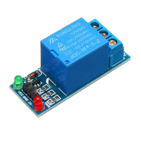
5v 1 Channel Relay Module Active Low Control
Relay 12v 4 Channel Module 4 Road/Channel Relay Module (with light coupling) 12V HW-316
4 Channel Isolated 5V 10A Relay Module opto coupler For Arduino PIC AVR DSP ARM1
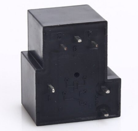
Relay 6 pin Coil 12Vdc 30A T90-dc12v-c
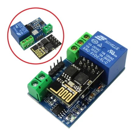
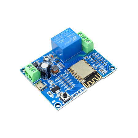
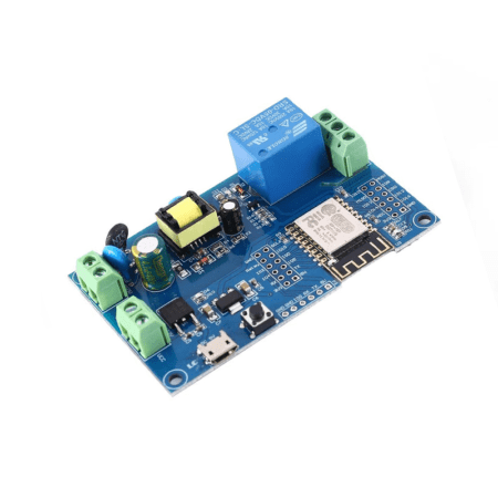
ESP8266 WiFi 5V 1 Channel Relay Module High Quality
Products With Similar Tags
Relay 12v 1 Channel Module 1 Road/Channel Relay Module
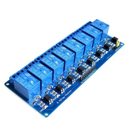
Relay 8 Channel 5V Module with Optocoupler Isolation – 10A Relay Board for Arduino, Raspberry Pi & Automation
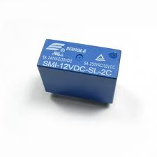
Relay 12V 8 pin 5A 250VAC 30VDC SMI-12VDC-SL-2C"
NE555 Delay Monostable Switch Module Time Delay Switch Delay On Vehicle Electrical Delay 12V With optocoupler
NE555 Delay Monostable Switch Module Time Delay Switch Delay On Vehicle Electrical Delay 12V