Description
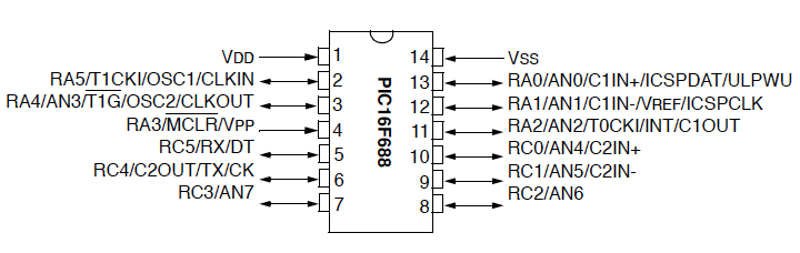
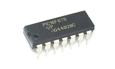
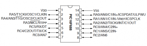
The PIC16F688 microcontroller has a built-in 10-bit ADC with eight input channels. The eight channels are available at RA0, RA1, RA2, RA4, RC0, RC1, RC2, and RC3. They have alternate labels, AN0-AN7, for this function, and are multiplexed into a single sample and Hold circuit. The?output of the sample and hold is?connected to the input of the A/D converter. The A/D conversion is successive approximation based and the 10-bit result is stored??into the ADC result registers ADRESH (A/D Result Higher byte) and ADRESL (A/D Result Lower byte). Each of these registers is 8-bit.
Pin diagram of the PIC16F688 microcontroller
Functional block diagram of ADC
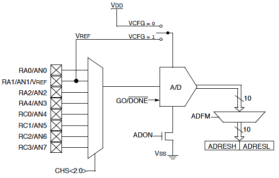
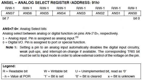
The functionality of the A/D module is controlled by three registers: ANSEL, ADCON0, and ADCON1.
The ANSEL register is used to configure the input mode of an I/O pin to analog. Setting the appropriate ANSEL bit High will cause all digital reads on the pin to be read as 0, and allow analog function on the pin to operate correctly. The state of ANSEL bits has no effect on digital O/P function. A pin with TRIS bit clear and ANSEL bit set will operate as digital O/P but the input mode will be analog.
ANSEL register bits
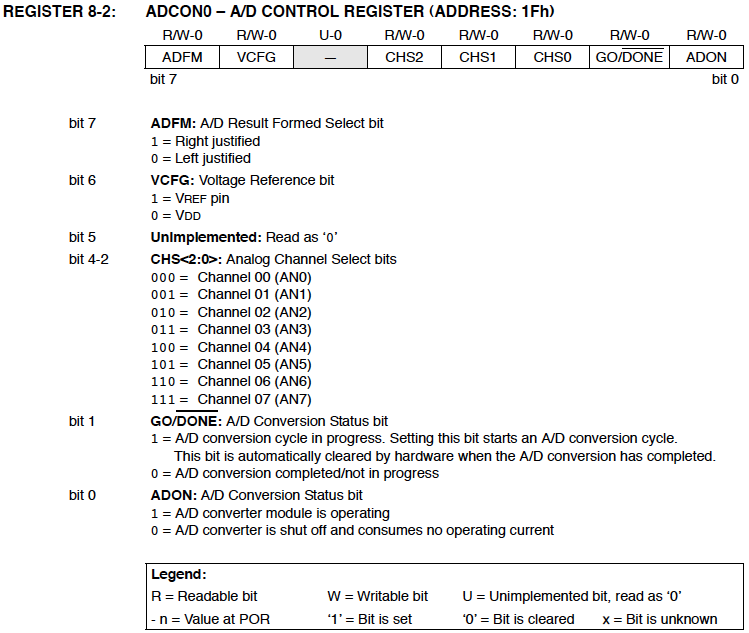
The ADCON0 register selects which analog input is to be measured. This is required, since there are several channels for?analog input but only one A/D converter circuitry.?The channel select bits CHS0-CHS2 of ADCON0 register controls which analog channel is connected to the internal Sample and Hold circuit. For example, if you want to measure input analog voltage at AN2 (RA2) pin, you should set CHS1, and clear CHS0 and CHS2. The reference voltage used in the A/D conversion process is software selectable to either Vdd or a voltage applied to the Vref pin (12). This is controlled by VCFG bit of ADCON0 register. If VCFG is set, the reference voltage for the A/D conversion will be the voltage applied at the Vref pin. Bit 0 (ADON) of ADCON0 is the On/Off switch for the A/D converter. When it is set, the ADC is On, and the PIC microcontroller consumes extra current. GO/DONE bit of ADCON0 is set to start an A/D conversion cycle. It is automatically cleared by hardware when the conversion is done. This bit can, therefore, be tested to see if the A/D conversion is completed or in progress.
ADCON0 register bits
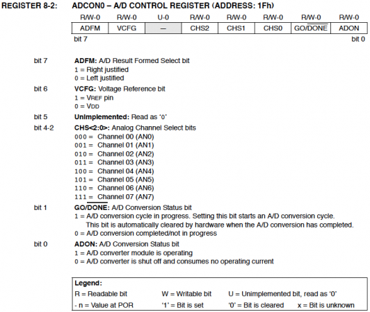
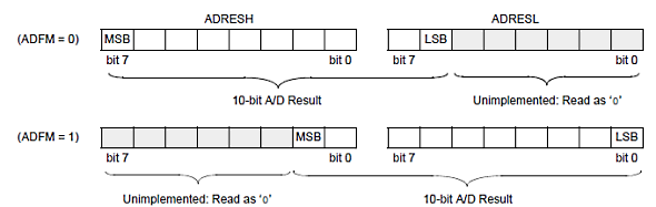
As mentioned earlier, the 10-bit digital output is held over two registers, ADRESH and ADRESL. You have a choice in how you want the 10-bit number stored into the two 8-bit registers. It can be right-justified by setting ADFM bit of ADCON0 so that bits 0:7 of the 10-bit result are held in ADRESL and bits 8:9 are stored in bits 0:1 of ADRESH. Similarly, clearing the ADFM bit shift the 10-bit output to the left. This is illustrated below.
Shifting the ADC result left or right with ADFM bit
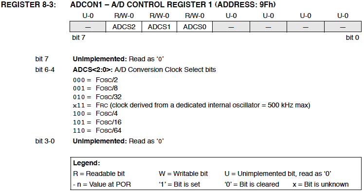
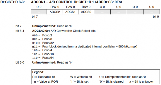
The ADCON1 register also plays an important role in programming the A/D module.?An ADC requires a clock source to operate. ADCS (A/D conversion Clock Select) bits of ADCON1 register are the selection bits for the A/D conversion clock. The conversion time per bit is defined as TAD?in PIC documentation from Microchip.?The A/D conversion cycle requires 11 TAD.?For correct conversion, the A/D conversion clock?(1/TAD) must be selected to ensure a minimum TAD?of?1.6 ?s. In PIC16F688, there are?seven possible clock options for A/D conversion that are software selected, as shown below.
Software selectable clock sources for A/D conversion
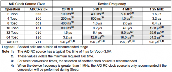
TAD?calculations for selected frequencies.
Acquisition Time
The input of the ADC has a sample and hold circuit, to ensure that the voltage?sampled is constant during the conversion process. This contains a holding capacitor that stores the sampled input voltage.?Acquisition time is the amount time required to charge the holding capacitor on the
front end of an analog-to-digital converter. The holding capacitor must be given?sufficient time to settle to the analog input voltage level before the actual?conversion is initiated, otherwise?the?conversion will be inaccurate. The source impedance of the input voltage and the impedance of the internal sampling switch are the two major factors to determine the required acquisition time. An increase in the source impedance?will increase the required acquisition time. Therefore, the maximum recommended source impedance for analog sources is 10K. ?A typical value of acquisition time is 20 ?s.
Programming the A/D module consists of the following steps:
1. Configure the analog/digital I/O using ANSEL register. All analog lines are initialized
as input in the corresponding TRIS registers.
2. Select the A/D input channel by setting the CHSx bits in the ADCON0?register. Also, select right- or left-justification (ADFM bit), and the reference voltage (VCFG bit).
3. Select the A/D conversion clock (ADCS bits), and enable the A/D module (ADON bit).
4. Wait the acquisition time.
5. Initiate the conversion by setting the GO/DONE bit in the ADCON0 register.
6. Wait for the conversion to complete.
7. Read and store the digital result.
A minimum wait of 2 TAD?is?required before the next acquisition starts.
Reference:?Datasheet for PIC16F688 from Microchip.