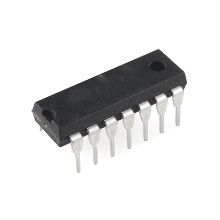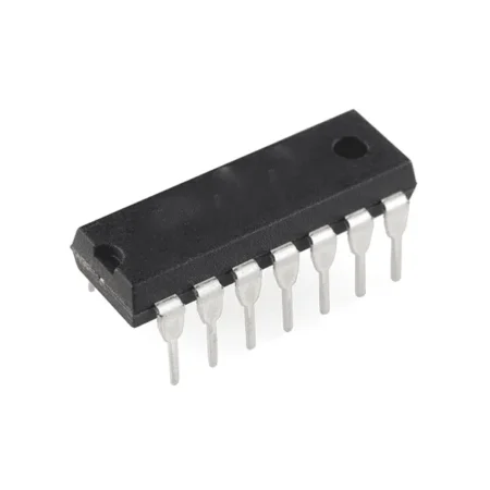
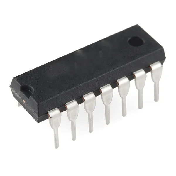

The CD4075 is a CMOS chip with three 3-input OR gates. Because each gate has three inputs and it has three gates inside, it’s usually called a Triple 3-Input OR Gate.
An OR gate is a logic gate that outputs HIGH if either of its inputs is HIGH. Each of the OR-gates in this chip has 3 inputs.
Pin Overview
| Pin Name | Pin # | Type | Description |
|---|---|---|---|
| VDD | 14 | Power | Supply Voltage (+3 to +15V) |
| GND | 7 | Power | Ground (0V) |
| A1 to A3 | 1, 3, 13 | Input | Inputs A of the three OR gates |
| B1 to B3 | 2, 4, 12 | Input | Inputs B of the three OR gates |
| C1 to C3 | 5, 8, 11 | Input | Inputs C of the three OR gates |
| Q1 to Q3 | 6, 9, 10 | Output | Outputs from the three OR gates |
What is a 3-input OR gate?
A 3-input OR gate works just like a normal OR gate. Its output becomes HIGH if any of the inputs are HIGH. Otherwise, its output is LOW.
Check the truth table below to see the result for any combination of inputs.

| Input A | Input B | Input C | Output Q |
|---|---|---|---|
| 0 | 0 | 0 | 0 |
| 0 | 0 | 1 | 1 |
| 0 | 1 | 0 | 1 |
| 0 | 1 | 1 | 1 |
| 1 | 0 | 0 | 1 |
| 1 | 0 | 1 | 1 |
| 1 | 1 | 0 | 1 |
| 1 | 1 | 1 | 1 |
How To Use the CD4075?
First of all, you need a power supply voltage of 3 to 15V. Some versions of the chip support up to 20V. Check the datasheet of your version of the chip for exact values.
To be able to use any of the OR gates in the chip, you need to first connect the VDD pin to the positive supply terminal and the GND pin to the negative supply terminal.
The A, B, and C pins are the inputs to the three OR gates in the IC.
The Q pins are the outputs from the OR gates.
CD4075 Example Circuit – RGB LED Color Switcher
In the following circuit, the 555 timer creates a clock signal for the CD4017 counter. The first six outputs of the 4017 IC are connected to the 3-input OR gates in a way that turns rotates between six different colors.
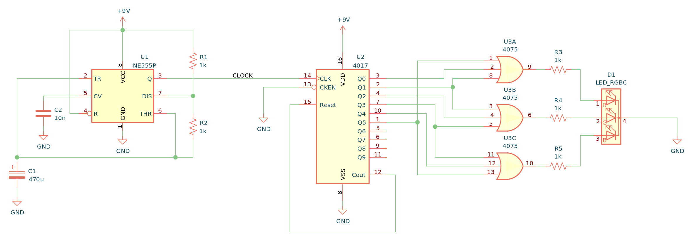
To build this you’ll need:
- A chip with 3-input OR gates such as the CD4075BE (U3)
- CD4017 Decade Counter (U2)
- 555 Timer IC (U1)
- RGB LED (D1)
- 5 x 1 kΩ resistors (R1-R5)
- Capacitor 470 µF (C1)
- Capacitor 10 nF (C2)
Alternatives and Equivalents for CD4075
You likely find the 4075 IC marked as CD4075, NTE4075, MC14075, HCF4075, TC4075, or HEF4075. Usually with a few extra characters at the end (Ex: CD4075BE).
This has to do with the manufacturer of the chip and the technology used. But the functionality and the pins are the same.
If they don’t have any of these chips in your local electronics store, check out my list of online stores where you can find components and tools for all your electronics projects.
Can’t find the 4075? Then try one of the following IC alternatives with 3-input OR gates:
- 74HC4075: Triple 3-input OR
4075 Datasheet
Download the PDF datasheet for the IC 4075 here:
CD4075B (Texas Instruments)