

Transistors، BJT Transistors، IGBT transistor، MOSFET Transistors
Mica Insulating Sheet for TO-3PL Transistor – 22x18x0.12mm – 1 Piece
Original price was: 1.50 EGP.1.00 EGPCurrent price is: 1.00 EGP.
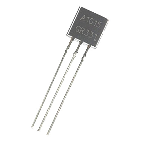
| Pin No. | Pin Name | Description |
| 1. | E | Emitter |
| 2. | C | Collector |
| 3. | B | Base |
Note: Complete technical details can be found in the A1015 Datasheet linked at the bottom of this page.
NTE290A, 2SA495, 2SA561, 2SA564A, 2SA573, 2SA675, 2SA705, 2SA850, 2SA999, KTA1015, BC212, BC257, BC307, BC557, 2N3494, 2SA781, KT3108A
The main use of 2SA1015 is for audio frequency amplifier applications. It can also be used for the switching purpose just like other PNP transistors. When use as an Audio frequency general purpose amplifier, can be operated in the active region. This transistor is further divided into four groups according to the DC current gain, O, Y, G, and L and has 140, 240, 400 and 700 hfe DC current gain respectively.
| Group | DC current gain (hfe) |
| O | 140 |
| Y | 240 |
| G | 400 |
| L | 700 |
Amplification factor usually determined in term of power, for calculating the current gain we use the formula:
Gain (hfe) = IC / IB
Where, IC is the collector current and IB is the base current of the circuit.
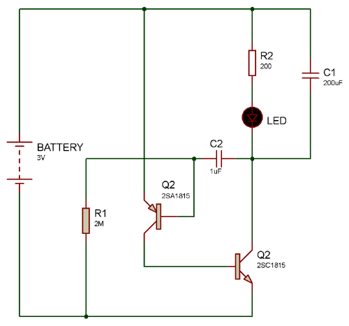
In the below circuit of LED flasher using 2SA1015, capacitor C1 and R1 used as frequency generator to Q1 transistor which is used as switch for Q2. And, Q2 is used for increasing the current. From capacitor C1 through R2 and LED, Q1 will work until the voltage drop increases across C1. As a result, Q2 starts conducting, and a current flows through LED and it turns ON.
While C1 discharged through R1 to a period of time, when C1 discharge out there would be no pressure to bias the base terminal of the Q1. Hence, the Q1 stop working which also stop Q2 to work. Therefore, LED turn OFF and C1 will start again and this cycle continues. And, the turning ON and OFF of LED seems as a flasher.
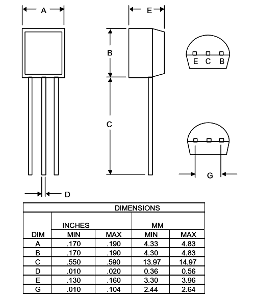
Component Datasheet
A1015 Transistor Datasheet






Tell us what you are building and we will help you find suitable components, modules, development boards and tools from our available range.