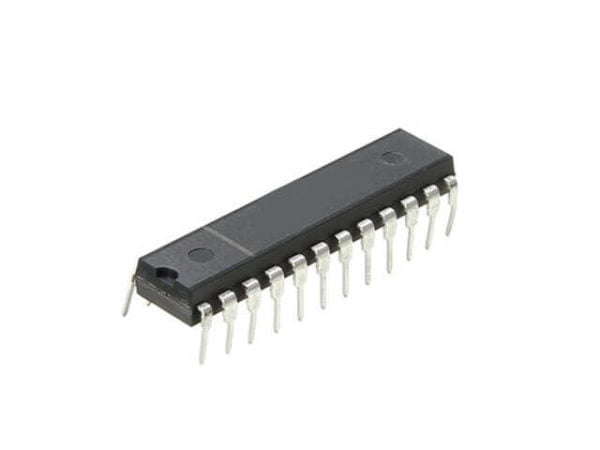
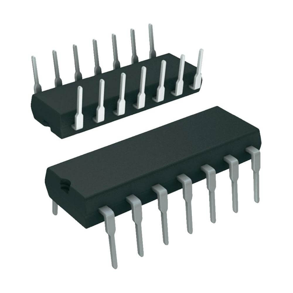

The 4026 is a monolithic integrated circuit fabricated in Metal Oxide Semiconductor technology available in DIP and SOP packages. The 4026 consists of a 5-stages Johnson decade counter and an output decoder which converts the Johnson code to a 7 segment decoded output for driving one stage in a numerical display. This device is particularly advantageous in display applications where low power dissipation and/or low package count are important. This device has CLOCK, RESET, CLOCK INHIBIT, DISPLAY ENABLE input and CARRY OUT, DISPLAY ENABLE, UNGATED “C” SEGMENT and 7 DECODED outputs (a to g). A high RESET signal clears the decade counter to its zero count. The counter is advanced one count at the positive clock signal transition if the CLOCK INHIBIT signal is low. Counter advancement via the clock line is inhibited when the CLOCK INHIBIT signal is high. Antilock gating is provided on the JOHNSON counter, thus assuring proper counting sequence. The CARRY-OUT (COUT) signal completes one cycle every ten CLOCK INPUT cycles and is used to clock the succeeding decade directly in a multi-decade counting chain.

|
Pin number |
Name |
Description |
|
1 |
CLK |
Clock?in, Increment the counter with each Positive clock pulse (LOW to HIGH). |
|
2 |
CI |
Clock?inhibit – when low, clock pulses increment the seven-segment. Freezes the counter when HIGH, active HIGH. |
|
3 |
DE |
Display?enable- chip will be ON when this pin is HIGH, and OFF if it is LOW. |
|
4 |
DEO |
Display?enable?out – for chaining 4026s |
|
5 |
CO |
?The CARRY-OUT (Cout) signal completes one cycle every ten CLOCK INPUT cycles and is used to clock the succeeding decade directly in a multi-decade counting chain |
|
6 |
F |
Connected to ?f? of the 7 segment. |
|
7 |
G |
Connected to ?g? of the 7 segment. |
|
8 |
VSS |
Ground PIN |
|
9 |
D |
Connected to ?d? of the 7 segment. |
|
10 |
A |
Connected to ?a? of the 7 segment. |
|
11 |
E |
Connected to ?e? of the 7 segment. |
|
12 |
B |
Connected to ?b? of the 7 segment. |
|
13 |
C |
Connected to ?c? of the 7 segment. |
|
14 |
UCS |
Ungated?C-segment – an output for the seven-segment’s?C?input which is not affected by the?DE?input. This output is high unless the count is 2, when it goes low. |
|
15 |
RST |
Reset?PIN, active HIGH. Reset the counter to 0 when HIGH. |
|
16 |
VDD |
Power supply PIN |
Download datasheet?