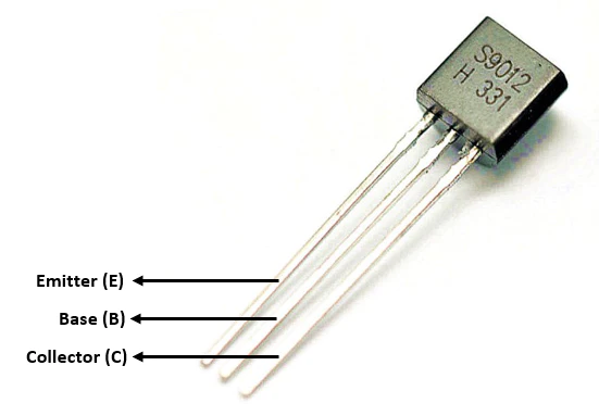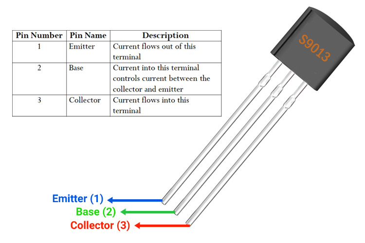

S9014 Transistor Pinout Configuration

| Pin No. | Pin Name | Description |
| 1 | Emitter | Current Drains out through emitter, normally connected to ground |
| 2 | Base | Controls the biasing of transistor, Used to turn ON or OFF the transistor |
| 3 | Collector | Current flows in through collector, normally connected to load |
Features
- Pre-Amplifier, Low Level, Low Noise NPN Transistor
- Current Gain (hFE), 60 to 1000 (good linearity)
- Continuous Collector current (IC) is 100mA
- Collector-Emitter voltage (VCEO) is 45 V
- Collector-Base voltage (VCB0) is 50V
- Emitter Base Voltage (VBE0) is 5V
- Transition Frequency 150MHz
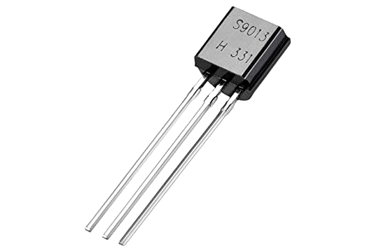
- Available in To-92 Package
Note: Complete Technical Details can be found at the datasheet given at the end of this page.
Complementary PNP for S9014
S9015
S9014 Equivalent Transistors
KSP06, KSP42, MPSA42, MPSW06
Alternative NPN Transistors
BC549, BC636, BC639, BC547, 2N2369, 2N3055, 2N3904, 2N3906, 2SC5200,2N551
Where to Use S9014 Transistors?
The S9014 is a low signal and low noise NPN transistor with a good hfe value of upto 1000 of high linearity this makes this transistor an ideal choice for designing Audio Frequency (AF) amplifiers or pre-amplifiers. This NPN transistor also has its counter PNP transistor (SS9015) which can be used to design class B amplifier in push-pull configuration. It also has good collector dissipation (power dissipation) of 0.4W to driver speakers of decent rating.
The transistor has a very low collector current of 100mA and hence it is not advised for switching or driving circuits. I have personally found these transistors being used in wireless security cameras and small game consoles where audio pre-amplification is required.
How to use S9014 Transistors?
The S9014 is commonly used to build pre-amplifier, but you may design your circuit based on your requirement. To build a pre-amplifier using a transistor we need to select a transistor that is of low signal and low noise with good hfe value and collector dissipation. The S9014 seems to satisfy us with all those parameters. A typical pre-amplifier circuit using S9014 is shown below.
![]()
The values of resistors R1, R2, R3 and R4 can be calculated by using the value of Vcc, Hfe and Ic. Some useful formulae for calculation is give below
Ib = Ic / hfe R1 = 1/2Vcc / .005 R2 = 1 / (Ic Ib)
You can find the design guidelines for building your own circuit in the given link.
Applications
- AF Pre-amplifiers
- Used as Class B amplifiers
- Low noise stage audio equipments
- Push-Pull Circuits
2D Model of S9014
If you are designing a PCB or Perf board with this component then the following picture from the Datasheet will be useful to know its package type and dimensions.